As the demands on networking grew, the NIC itself had to evolve. This evolution happened in three stages:
The NIC evolution: NIC → HCA → DPU
An RDMA-capable NIC. The key innovation: the HCA implements the transport protocol entirely in hardware. Applications post Work Requests directly to the HCA via a memory-mapped queue — no syscalls, no kernel involvement. The HCA DMA's data directly to/from GPU or CPU memory.
Stage 1 -- The classic NIC Moves packets between the kernel's network stack and the wire. The CPU processes every packet. Fine for 1GbE or 10GbE. Becomes a bottleneck at 100GbE because the CPU simply cannot process packets fast enough.
What RDMA actually does -- the queue model
To understand why the HCA exists, you need to understand what RDMA asks the network to do. In a standard TCP socket application, the CPU calls send(), the kernel copies data into a socket buffer, the kernel's network stack builds packets, and the NIC transmits them. The CPU is involved at every stage.
RDMA replaces this with a queue-based model. An application registers a memory buffer with the RDMA driver. It then posts a Work Queue Element (WQE) -- a descriptor saying "send the data at this memory address to that remote host's memory at that address." The CPU's job ends here. It has posted a work request and returned to other work.
The NIC processes the WQE directly. It reads from the registered memory buffer, builds the RDMA packets, transmits them, handles acknowledgements, retransmits if needed, and writes a completion entry when done. The CPU checks the Completion Queue periodically -- not to process packets, but to confirm the transfer finished.
This model creates three queues per connection:
- Send Queue -- WQEs for outbound transfers (send, write, read)
- Receive Queue -- buffers posted for inbound transfers
- Completion Queue -- completed WQEs posted by the NIC when done
A Queue Pair (QP) is a send queue plus a receive queue. Each RDMA connection between two endpoints uses a QP. A single DGX node running AllReduce across 255 peers maintains 255 active QPs simultaneously. The QP number appears in ibstat output and in RDMA diagnostic logs. When a packet is dropped and the RDMA transport cannot recover, the QP enters an error state -- which is what State: Error in ibstat means. The GPU on that QP is effectively disconnected from the AllReduce until the QP is reset.
Why this matters for diagnostics: The Verbs API is the programming interface that applications use to post WQEs and check completion queues. NCCL uses Verbs internally. When NCCL logs "QP transition to error state" or "SRQ limit reached," it is reporting RDMA layer events. Understanding the queue model makes these messages interpretable rather than opaque.
Stage 2 -- The HCA (Host Channel Adapter) RDMA moves packet processing entirely into the NIC hardware. The CPU posts a Work Request and checks for completion -- it never touches the actual data. The HCA has its own processor, its own memory, and handles all transport protocol processing in silicon. This is what a ConnectX-7 is when configured for InfiniBand: an HCA.
Stage 3 -- The DPU (Data Processing Unit) The BlueField series goes further. A DPU is a fully programmable SmartNIC with an embedded Arm CPU complex (16 cores in BlueField-3), running a full Linux OS independently of the host. It can offload not just RDMA transport but also:
- OVS (Open vSwitch) -- replacing CPU-based virtual switching
- NVMe-oF (storage protocol) -- presenting remote NVMe as local drives
- TLS/IPsec termination -- encrypting all traffic without host CPU involvement
- Firewall and security policy -- enforced in hardware
NVIDIA BlueField-3 DPU — the infrastructure co-processor
A DPU (Data Processing Unit) is a programmable SmartNIC with an embedded multi-core Arm CPU complex running a complete Linux OS — independently of the host server. Think of it as a small server inside your server, dedicated entirely to running infrastructure services.
The key distinction from a NIC or HCA: the DPU has its own CPU, memory, and operating system. It boots separately from the host. It can be patched and updated without touching the host. In a cloud environment, the infrastructure team owns the DPU — the tenant owns the host. The DPU enforces security and network policy that the tenant cannot see or modify.
Where BlueField fits in NVIDIA's lineup
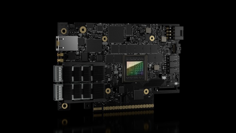
Figure: Official NVIDIA BlueField-3 DPU image. This gives a concrete physical anchor for the exact DPU generation referenced in this section.
In a DGX H100 or H200, there are 10 ConnectX-7 adapters per node: 8 single-port HCAs for the compute fabric, and 2 dual-port CX7 cards (Slot1 and Slot2) for the storage and in-band management fabric. All 10 are ConnectX-7. The DPU architecture -- where a BlueField card runs its own independent ARM Linux OS and handles storage offload on the card itself -- appears in the DGX B200, not the H100 or H200. The distinction matters operationally: on an H100/H200 node, the NVMe-oF initiator stack runs on the host CPU using the Slot1/Slot2 CX7 ports as standard NICs. On a B200 node, the BlueField-3 HCAs run the initiator on their own ARM cores independently of the host.