What ECN is, and is not
ECN is commonly misunderstood as a replacement for PFC. It is not. ECN does not prevent packet loss. It does not pause senders. It does not provide losslessness guarantees. What ECN does is signal congestion before the buffer reaches the drop threshold, giving senders time to reduce their rate before PFC pausing is needed.
Think of it this way: PFC is the emergency brake. ECN is the warning light on the dashboard. In a well-configured fabric, the warning light fires early enough that you slow down before you need the emergency brake. The emergency brake is still there -- you just rarely need it.
ECN mechanics — how congestion marking works
RED (Random Early Detection) is the algorithm switches use to decide which packets to mark with CE. Drag the slider to see how marking probability changes with buffer depth.
Buffer < 30%30% ≤ Buffer ≤ 80%Buffer > 80%The CE bit and ECT codepoints
ECN is defined in RFC 3168. It uses two bits in the IP header's Differentiated Services field (the same byte that carries DSCP markings):
IP Header DSCP byte (8 bits):
  Bits 7-2: DSCP marking (6 bits) -- QoS class, e.g. DSCP 26 for RoCEv2
  Bit 1-0:  ECN field (2 bits)

ECN codepoints:
  00 -- Not-ECT: sender does not support ECN
  01 -- ECT(1): ECN-capable transport (variant 1)
  10 -- ECT(0): ECN-capable transport (variant 0, more common)
  11 -- CE: Congestion Experienced -- set by switch to signal congestion
When a RoCEv2 packet is sent, the ConnectX-7 NIC sets the ECN field to ECT(0) -- indicating "I support ECN, please mark me instead of dropping me." When the packet passes through a congested switch, the switch changes the ECN field to CE -- "I have experienced congestion."
The receiver sees the CE-marked packet and sends a CNP (Congestion Notification Packet) back to the sender. The sender's NIC firmware receives the CNP and reduces its injection rate. This rate reduction is the DCQCN algorithm.
How the switch decides to mark
The switch uses a marking algorithm to decide which packets to mark with CE. The standard algorithm is RED (Random Early Detection):
If buffer depth < min_threshold:
    -> Do not mark. Traffic is flowing freely.

If min_threshold <= buffer depth <= max_threshold:
    -> Mark with probability P, where P increases linearly
      from 0 at min_threshold to max_probability at max_threshold

If buffer depth > max_threshold:
    -> Mark all packets
    (or drop, depending on configuration)
The key parameters:
min_threshold -- Buffer depth below which no marking occurs. Should be set well below the PFC headroom threshold so ECN starts working before PFC is needed.
max_threshold -- Buffer depth at which maximum marking probability is applied. Should be below the PFC pause threshold.
max_probability -- The maximum fraction of packets marked at max_threshold. Typically 0.1 to 0.5 (10%-50%).
In practice on Spectrum-X switches, these thresholds are configured in bytes:
# Leaf switch terminal
# Configure ECN marking thresholds for priority 3 (RoCEv2)
nv set qos congestion-control profile roce \
    min-threshold 150000 \
    max-threshold 1500000 \
    probability 100
nv config apply
The relationship between ECN thresholds, PFC headroom, and maximum buffer depth must be carefully ordered:
ECN min-threshold < ECN max-threshold < PFC headroom threshold < Buffer maximum
If this ordering is violated -- for example, if ECN marks at max_threshold but PFC pauses at a lower threshold -- ECN marks will trigger pauses rather than rate reductions, defeating the purpose.
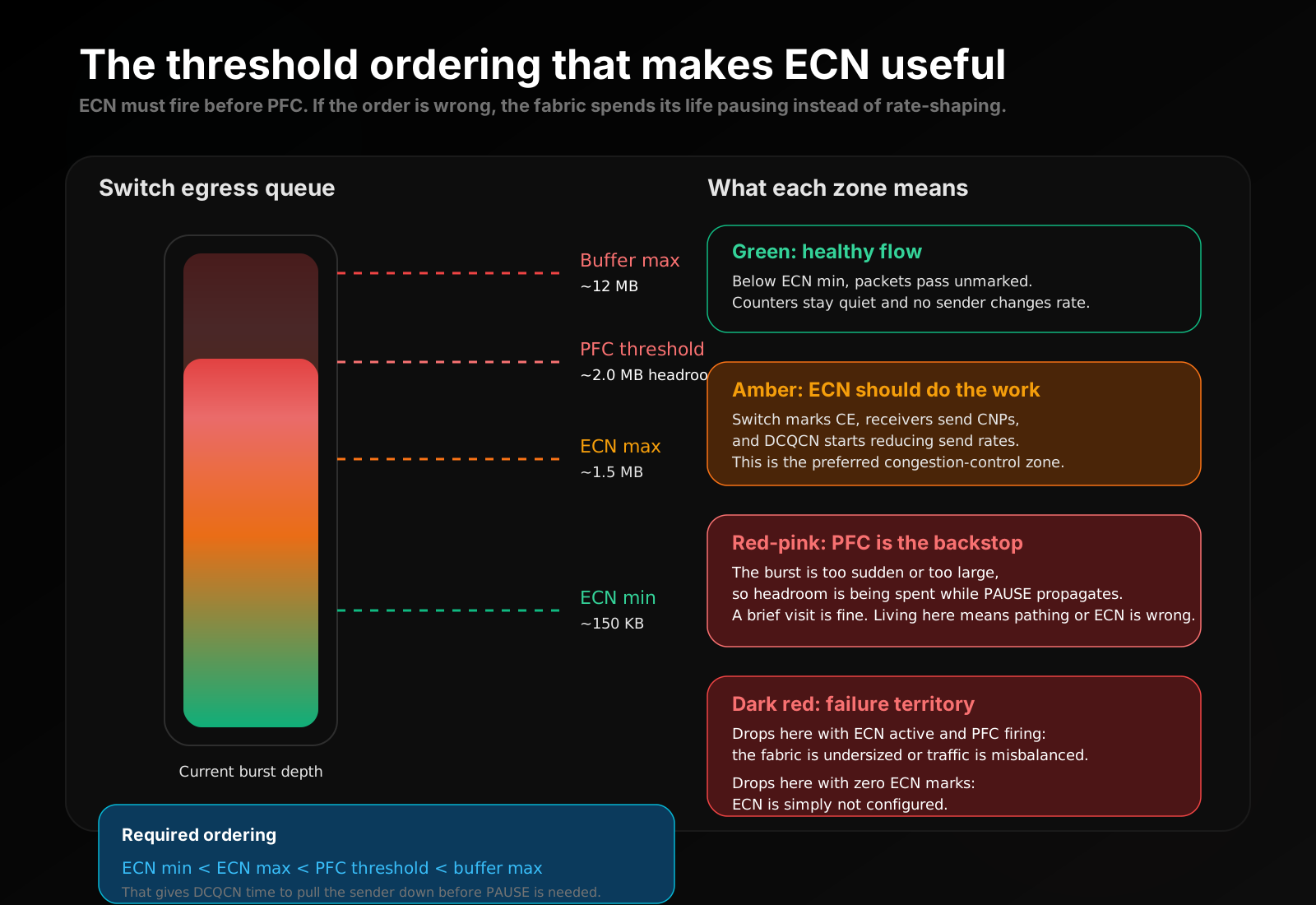
Figure: The ordering matters more than the absolute values. ECN has to start early enough that DCQCN can reduce the sender before PFC headroom is consumed.